.
Touch sensor switch using inverters
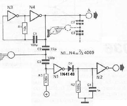
This touch sensor switch can is designed using inverters (N1, N2)and some common electronic components. In standby state at the entrances of N1 there is a signal produced by oscillator N3/N4. At the touch sensor hand capacity forms a bridge to the ground for the 1MHz signal so that the voltage signal at the entrance of N1 decreases more (at the exit of N2 is logical 1). After the release of contact, a signal charge C4 through D1 Mhz, so the output of N2 is 0 logic after short time.
Installation can be powered with a DC voltage between 3 and 15 volts (maximum current of 2 mA is absorbed).
Electronic Circuits:
Circuit Diagram:

- Log in to post comments


